|
|
|
|
|
How does a REED Concrete
Pump work?
The operation of the concrete
pump encompasses the use of hydraulic
and electrical systems. The concrete pump
is designed to safely pump
wet concrete through a delivery system
of pipes and hoses within its published
ratings and
specifications.
Stability of the concrete
pump during operation is provided by the
outriggers and front jack. Controls for
the outriggers are located on the sides
of the concrete pump.
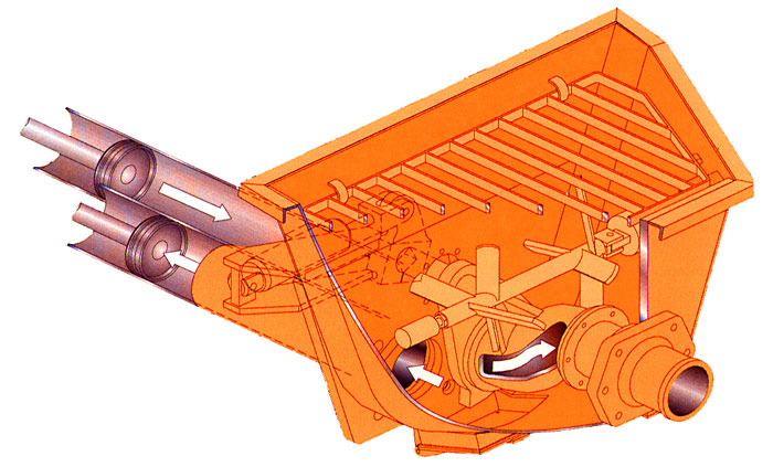
The pumping system employs
a S-Tube design valve system. This system
incorporates material cylinders linked
to hydraulic cylinders that cycle alternately.
With concrete material in the hopper and
the pump operating, a material cylinder
retracts, drawing material into the cylinder.
At full retraction of the cylinder, a
signal is sent to both the S-tube swing
cylinder and the drive cylinder directional
valves causing the s-tube to shift position
to the fully loaded material cylinder
and the drive cylinders to change direction.
The concrete piston of the loaded cylinder
then pushes the material through the s-tube
and into the delivery lines. The shifting
from one cylinder to the other cylinder
takes place providing a continuous flow
of material through the delivery piping
system. The pump can be operated at the
control panel or can be operated from
the remote control.
|
|
|
|
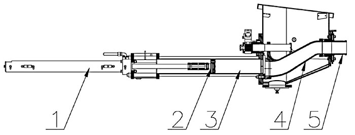
The hydraulic oil flow created
by the hydraulic pump pushes the drive
cylinder pistons inside the drive cylinders
(1) alternately back and forth. Because
the drive cylinders and concrete pistons
(2) inside the concrete cylinders (3)
are linked together, the pistons move
synchronously.
When a drive cylinder retracts along with
the concrete piston, concrete will be
sucked from the hopper into the concrete
cylinder. Simultaneously, the other drive
cylinder and concrete piston are extended
toward the hopper. The concrete piston
will push concrete from the concrete cylinders
through the S-Tube (4) and out to delivery
system (5).
Next, the pump switches at the end of
the stroke, causing the s-tube valve to
shift to the other concrete cylinder which
has sucked and filled the cylinder with
concrete, starting the next cycle.
Reverse pumping links the concrete piston
in the suction stroke and S-Tube valve
to suck concrete from the s-tube instead
of the hopper. As a result, the concrete
piston pumps concrete into the hopper.
The power for operation of the concrete
pump is provided by the engine, which
drives the hydraulic pumps.
All functions for operation of the concrete
pump can be accomplished from the local
controls mounted on the side of the unit.
Optional hand-held cable or radio remotes
enable the pump to be operated away from
a remote distance.
|
|
HYDRAULIC SYSTEM DESCRIPTION:
The hydraulic system of
the concrete pump consists of three separate
circuits and although integrated, each
is designed to perform a particular function
within the operation of the concrete pump.
The three circuits utilized are:
Main Pump Circuit Controls operation
of the hydraulic drive cylinders.
S-Tube Shift Circuit Controls operation
of shifting the s-tube from one material
cylinder to the other.
Auxiliary Circuit Controls the operation
of the agitator and other auxiliary equipment.
For the purpose of making the operation
of each circuit easier to understand,
they are being described separately.
|
|
MAIN PUMP CIRCUIT:
The main hydraulic pump
is a variable displacement axial piston
pump of swashplate design. The pistons
run along the swashplate which is capable
of being tilted. This tilting changes
the angle of the swashplate and thus the
stroke length of the pistons, which in
turn varies the displacement of fluid.
The larger the angle of the swashplate,
the greater the flow. The angle of the
swashplate is varied by the volume control
that works in conjunction with the load
sense feature of this pump.
The main hydraulic pump
is driven directly by the engine or electric
motor. When the engine is running, PUMP
switch in the OFF position and the VOLUME
control minimized, there is no demand
placed on the pump. This is referred to
as the pump being de-stroked, meaning,
it is only producing a minimal amount
of flow to enable the lubrication of the
pump. This lubrication exists regardless
of whether the engine is at idle or maximum
RPM.
The main pump circuit is
equipped with a manifold that is drilled
and ported to accommodate the relief valve,
check valve, flow control and the pilot
operated directional valve. The cycle
valve is a directional spool valve with
electro hydraulic solenoid operation.
Its purpose is to direct the flow of oil
from the main hydraulic pump to one or
the other hydraulic drive cylinders.
To energize the pump circuit,
use the adjustable throttle control to
set the engine speed at maximum RPM. Open
the VOLUME control to any range from 0
to FULL. In so doing, the load sense is
alerted to the demand and places the pump
on stroke. The pump will now produce the
flow in proportion to the amount by which
the volume control has been opened. Since
the PUMP switch is OFF, the flow from
the hydraulic pump is fed to the main
directional valve, thru the valve, and
then returns to the hydraulic tank.
To energize the cycling
circuit, the PUMP switch must be ON. When
this is done, an electrical signal is
generated which in turn energizes the
coils of the main directional pilot valve
and also activates the S-Tube directional
valve.
The material pumping action
is the result of the two material cylinders
cycling on an alternate basis. This alternating
cycling is controlled by an electrical
signal that is generated by the proximity
sensors located in the flush box at the
end of each material cylinders suction
or retraction stroke.
As the piston coupler passes
under the proximity sensor, it generates
an electrical input signal that is sent
to the logic controller, designed to control
the alternating action of the material
cylinders and to synchronize the movement
of the s-tube. The output signal from
the logic controller is used to energize
the coils of the main directional pilot
valve as well as that of the stube directional
valve.
As protection to the main
pump circuit against excessive pressure,
a relief valve has been installed and
set. Thus when the system pressure reaches
the maximum factory settings, the relief
valve opens directing the oil back to
the tank.
|
|
MAIN PUMP CIRCUIT OPERATIONAL
SEQUENCE:
It can be noted in the schematic
and the diagram below that the main pressure
and flow is only directed to one side
of the hydraulic drive cylinder. In this
instance, it is directed to the head side
or piston side of the double acting drive
cylinder.
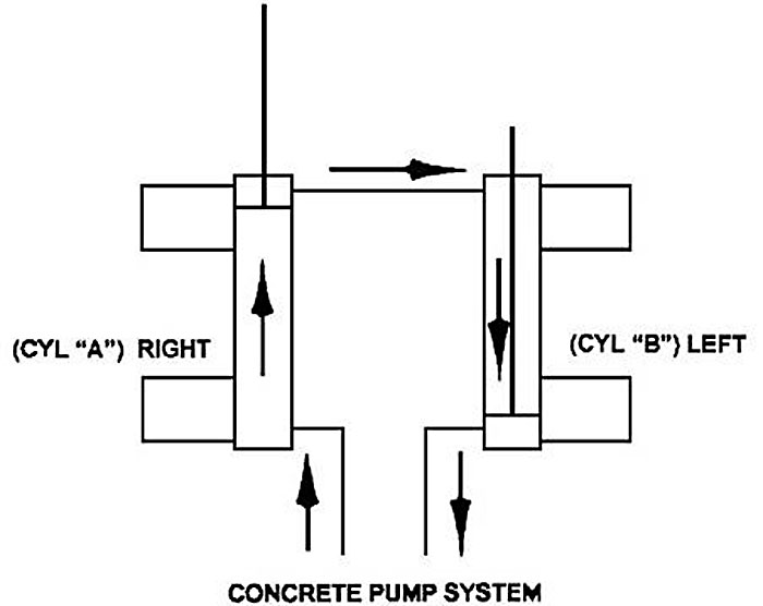
The hydraulic drive cylinders
are identical. Because only one cylinder
is pressurized at a time, a means is required
to assist in the retraction of the opposite
cylinder. This is accomplished by connecting
the rod sides of the cylinders together,
forming a slave loop. In so doing, the
hydraulic fluid that exists in the rod
side of the extending cylinder (CYL A)
is transferred to the rod side of the
other cylinder (CYL B) causing it to
retract simultaneously. The oil in the
head side of CYL B is then forced out
as it retracts and free flows through
the directional valve back to the hydraulic
tank or system.
With this arrangement of
connecting the two cylinders together,
it is possible for various reasons, such
as leakage around the piston seals, that
more oil exists on the rod side of the
cylinder than is required. When this condition
exists, some hydraulic oil remains at
the rod end of the cylinder being extended
while the other cylinder is fully retracted.
As a result, the cylinder will not completely
extend and thus short strokes, which will
also happen to the other cylinder on the
next cycle.
This condition can be corrected
by actuating and holding the STROKE CHANGE
switch on the electrical control box until
extending cylinder is fully extended.
Hydraulically, this is accomplished by
use of the check valves installed on both
cylinders. By holding the STROKE CHANGE
switch, you have interrupted the cycle
and are forcing more oil into the head
side of the extending cylinder. Since
that cavity is full, pressure is built
up in the rod side of the fully retracted
cylinder, which unseats the head-side
check valve and forces the excess oil
out of the slave loop and back to the
tank. Once the extending cylinder has
reached its full stroke, regular operation
can continue.
Short stroking can also
occur from incorrect proximity sensor
location or leaking check valves.
|
|
S-TUBE CIRCUIT:
Since there is only one
outlet for the pumping material, a means
is required to transfer the material from
the material cylinder to the outlet and
into the delivery line. To accomplish
this, an s-tube is installed in the hopper.
Since there are two material cylinders
and one s-tube, the s-tube must be shifted
from one material cylinder to the other,
whichever one is loaded with the pumping
material.
The s-tube shift hydraulic
circuit is of the open center type, meaning
that when the control valves are in the
neutral position, the internal passages
of the valves are open, allowing the hydraulic
fluid to return to the tank. With the
engine running the hydraulic pump is operating,
producing a flow of oil which, with no
control energized, will pass through the
shift circuit on its way back to tank.
To meet the flow and pressure
requirements of the shift circuit, one
section of a tandem pump is used. Note:
a single pump may be used if unit is not
required for auxiliary equipment. The
tandem hydraulic pump is of the gear pump
design with a fixed displacement, meaning
it is designed to constantly produce the
same displacement at a pre-set maximum,
depending on engine rpm. The tandem gear
pump is directly connected to and driven
through the main hydraulic pump. In addition
to the hydraulic pump, the s-tube shift
circuit consists of a manifold, an accumulator,
solenoid valve cartridges, a solenoid
directional valve, and 1 or 2 hydraulic
shift cylinders. The following is offered
to describe the function of each in the
system.
|
|
S-TUBE CIRCUIT MANIFOLD:
Like the main hydraulic
circuit, the shift circuit is also equipped
with a manifold block. It contains an
unloader cartridge, relief cartridge and
solenoid valve cartridges. A solenoid
operated directional valve is mounted
on top of the block and a s-tube selector
control valve is located on front of the
block. Each of these components is designed
to perform a particular function in the
swing circuit as explained in the following
descriptions:
RELIEF CARTRIDGE This cartridge is used
to divert the pump flow from going to
the accumulator once its capacity has
been reached, directing it back to tank.
It becomes operational when the unloader
cartridge setting has been reached, acting
as a dump valve.
UNLOADER CARTRIDGE This pressure sensitive
cartridge is used to protect the system
from excessive pressure and to limit the
amount of pressure being applied to the
accumulator by hydraulically signaling
the relief cartridge to open once the
unloader setting has been reached. The
unloader will also redirect the oil back
to the accumulator when it senses a drop
in system pressure, when the hydraulic
cylinder shifts for example.
SOLENOID VALVE CARTRIDGE There are two
(2) of these cartridges used in the circuit.
Both, which may be referred to as a dump
valve, are designed into the circuit as
SAFETY VALVES. Their purpose is to automatically
relieve pressure from the shift circuit
as commanded by the emergency stop circuit.
At start up, the normally open cartridges
are open to tank so the shift circuit
can not build any pressure. When the emergency
stop circuit is reset, an electrical signal
is generated which energizes the solenoids,
closing the cartridges and allowing the
shift circuit to pressurize. When the
emergency stop function is activated or
the key switch turned off, the power is
taken away from solenoids, causing the
cartridges to open and dump shift circuit
pressure back to tank.
SOLENOID DIRECTIONAL VALVE This valve
is a directional control valve that is
shifted by electronically activated solenoids.
Its purpose is to direct the flow of oil
stored in the accumulator to one or the
other end of the shift cylinder based
on the signal received by the logic controller
that was generated by the proximity sensor.
SHIFT BALL VALVE This is a manual ball
valve and is used to control the speed
of the s-tube shift. with valve fully
opened, the flow is unrestricted, causing
a fast hard shift of the s-tube. When
the valve is closed, the shift is slower
as the flow must now pass through an orifice.
ACCUMULATOR The accumulator is incorporated
into the shift circuit to provide instant
pressure and volume for the shifting of
the s-tube, which cannot be obtained under
normal circumstances. An accumulator is
a hydraulic reservoir that retains the
hydraulic fluid under high pressure. The
accumulator contains a rubber bladder
on the inside of the reservoir. The bladder
is pre-charged with dry nitrogen. In the
application of the shift circuit, the
hydraulic fluid is pumped into the accumulator
at a higher pressure than that inside
the bladder. This compresses the bladder
building up high pressure within the accumulator
that is retained until released.
|
|
S-TUBE CIRCUIT OPERATIONAL
SEQUENCE:
In the operational sequence
of the shift circuit with the engine at
full RPM, the tandem pump is producing
its rated displacement. The flow is going
through the system and is being dumped
or directed back to the tank thru the
solenoid cartridges of the s-tube circuit
manifold.
When the HORN/RESET switch
is placed to RESET, an electrical signal
closes the solenoid cartridges. When this
occurs the hydraulic fluid is now directed
to the accumulator where it starts compressing
the bladder and building up pressure.
When the pressure in the shift circuit
reaches a setting of the unloader valve,
the unloader valve activates causing the
relief cartridge to open. The open relief
valve now directs the oil flow from the
pump back to the tank instead of continuing
to pressurize the accumulator. A check
valve retains the pressure in the swing
circuit and prevents the fluid from going
back into the pump line.
In the main pump circuit
description it was described how an electrical
signal was generated by the proximity
sensor which was sent to the logic controller
and used to control the alternating action
of the hydraulic drive cylinders. This
same signal is also used to shift the
s-tube so that its movement is synchronized
with that of the hydraulic drive cylinder,
shifting the s-tube to the material cylinder
which is ready to extend (normal forward
operation).
The electrical signal activates
the solenoid coil of the directional valve,
shifting the spool to the appropriate
side. The accumulator then releases, exhausting
the fluid which flows through the directional
valve and is directed to the appropriate
side of the shift cylinder. As soon as
the shift is made the accumulator is refilled
immediately and the sequence starts all
over again.
AUXILIARY CIRCUIT:
The auxiliary circuit has
been designed and installed for the purpose
of operating the hydraulic function of
the auxiliary equipment on the unit, primarily
the agitator. This function is that of
the agitator rotation for mixing the material
in the hopper and feeding of the concrete
cylinders.
The flow and pressure requirements
for the auxiliary circuit are met by employing
the second stage or section of the same
tandem pump used on the s-tube shift circuit.
With the engine running and throttle set
to maximum RPM, the flow from the tandem
pump is directed to a single spool directional
control valve. This circuit also utilizes
a solenoid valve cartridge or dump valve,
designed as a safety valve with the purpose
of preventing flow to the auxiliary circuit
as commanded by the emergency stop circuit.
At start up, the normally open cartridge
directs the oil flow from the tandem pump
to tank, prohibiting function of the auxiliary
circuit. When the emergency stop circuit
is reset, an electrical signal is generated
to energize the solenoid, closing the
cartridge and blocking flow directly back
to tank, instead allowing the flow to
the single spool directional control valve
for operation. The directional control
valve has relief cartridge to protect
the system against excessive pressure
When the valve lever is
activated the agitator will rotate in
forward direction as hydraulic fluid is
directed to that side of the motor. Rotation
can be reversed by moving lever in other
direction.
|
|
|
|
|